Notice: This blog post was originally published on Indeni before its acquisition by BlueCat.
The content reflects the expertise and perspectives of the Indeni team at the time of writing. While some references may be outdated, the insights remain valuable. For the latest updates and solutions, explore the rest of our blog
In this post, we will cover the benefits introduced by Virtual Port-Channel (vPC) for First Hop Redundancy Protocols (FHRP).
Hot Standby Router Protocol (HSRP) and Virtual Router Redundancy Protocol (VRRP) are two of these FHRPs.
HSRP is Cisco proprietary whereas VRRP is a standard-based protocol and allows interoperability between different vendors.
vPC enhances FHRPs by allowing them to operate in active-active mode at data plane while at control plane the FHRP still works in active-backup mode.
The above statement considers active as the ability to forward traffic and it is just a coincidence with the HSRP state. In VRRP, the master forwards the traffic, whereas the backup does not.
Coming back to the vPC use case, at the control plane, the active router is still responsible to reply to ARP Requests with the virtual MAC address. In case the ARP request is received by the backup router, the ARP request is forwarded to the active router through the VPC peer-link which then replies with the virtual MAC address.
The feature that allows FHRPs to work in active-active mode at data plane is vPC built-in and there is no additional configuration required to enable it.
The active-active operation mode is facilitated by imposing G bit (Gateway bit) for the FHRP virtual MAC in the MAC address table on both vPC peer devices. We are going to see what it means later.
Let’s see an example using VRRP as FHRP on two Nexus devices.
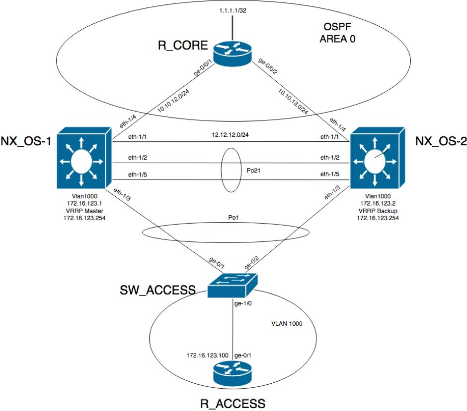
This is the network diagram:
R_ACCESS has a default gateway 172.16.123.254 which is the virtual IP address configured in VRRP.
R_ACCESS#show ip route

Gateway of last resort is 172.16.123.254 to network 0.0.0.0

S* 0.0.0.0/0 [1/0] via 172.16.123.254
 172.16.0.0/16 is variably subnetted, 2 subnets, 2 masks
 C 172.16.123.0/24 is directly connected, GigabitEthernet0/1
 L 172.16.123.100/32 is directly connected, GigabitEthernet0/1
 R_ACCESS#
The ARP table on R_ACCESS shows the virtual MAC address for the default gateway IP:
R_ACCESS#show ip arp
 Protocol Address Age (min) Hardware Addr Type Interface
 Internet 172.16.123.254 0 0000.5e00.0101 ARPA GigabitEthernet0/1
 Internet 172.16.123.100 - fa16.3e8b.ce06 ARPA GigabitEthernet0/1
 R_ACCESS#
A best practice recommendation is to have at control-plane the active router the same device that is the vPC primary peer device.
In this case, NX_OS-1 is the master router and in the same time it is the primary peer.
NX_OS-1# show vrrp detail

Vlan1000 - Group 1 (IPV4)
 State is Master
 Virtual IP address is 172.16.123.254
 Priority 110, Configured 110
 Forwarding threshold(for VPC), lower: 1 upper: 110
 Advertisement interval 1
 Preemption enabled
 Authentication text "VRRP_AU"
 Virtual MAC address is 0000.5e00.0101
 Master router is Local
NX_OS-1# show vpc
 Legend:
 (*) - local vPC is down, forwarding via vPC peer-link

vPC domain id : 21
 Peer status : peer adjacency formed ok
 vPC keep-alive status : peer is alive
 Configuration consistency status : success
 Per-vlan consistency status : success
 Type-2 consistency status : success
 vPC role : primary
 Number of vPCs configured : 1
 Peer Gateway : Disabled
 Dual-active excluded VLANs : -
 Graceful Consistency Check : Enabled
 Auto-recovery status : Disabled
 Delay-restore status : Timer is off.(timeout = 30s)
 Delay-restore SVI status : Timer is off.(timeout = 10s)
 Operational Layer3 Peer-router : Disabled

vPC Peer-link status
 ---------------------------------------------------------------------
 id Port Status Active vlans
 -- ---- ------ -------------------------------------------------
 1 Po21 up 1000

vPC status
 ----------------------------------------------------------------------------
 Id Port Status Consistency Reason Active vlans
 -- ------------ ------ ----------- ------ ---------------
 1 Po1 up success success 1000
Please check “show vpc consistency-parameters vpc” for the consistency reason of down vpc and for type-2 consistency reasons for any vpc.
NX_OS-1#
The Port-Channel between the access switch and the two Nexus devices is up:
SW_ACCESS#show etherchannel summary
 Flags: D - down P - bundled in port-channel
 I - stand-alone s - suspended
 H - Hot-standby (LACP only)
 R - Layer3 S - Layer2
 U - in use N - not in use, no aggregation
 f - failed to allocate aggregator

M - not in use, minimum links not met
 m - not in use, port not aggregated due to minimum links not met
 u - unsuitable for bundling
 w - waiting to be aggregated
 d - default port

A - formed by Auto LAG

Number of channel-groups in use: 1
 Number of aggregators: 1

Group Port-channel Protocol Ports
 ------+-------------+-----------+-----------------------------------------------
 1 Po1(SU) LACP Gi0/1(P) Gi0/2(P)

SW_ACCESS#
R_CORE is running OSPF with the two Nexus devices for end-to-end reachability:
R_CORE#show ip route
 172.16.0.0/24 is subnetted, 1 subnets
 O 172.16.123.0 [110/41] via 10.10.13.2, 00:01:57, GigabitEthernet0/2
 [110/41] via 10.10.12.2, 00:03:30, GigabitEthernet0/1
 R_CORE#
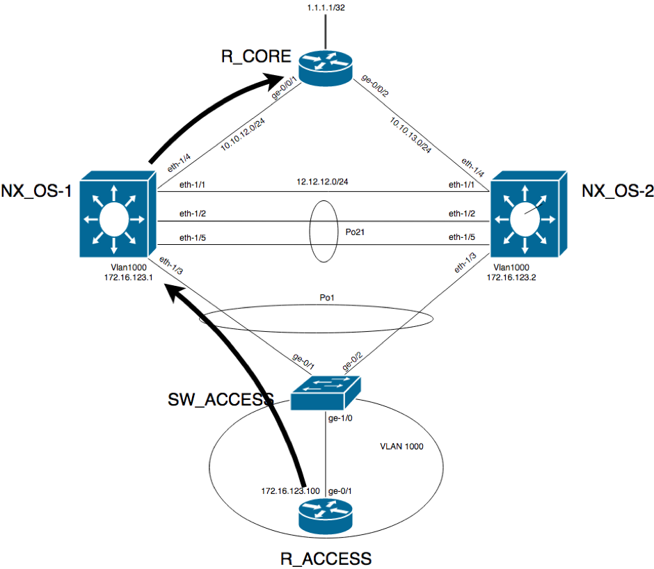
This being said, when the traffic from R_ACCESS needs to go R_CORE (that is, pass through one of the two Nexus devices), it will reach the access switch. At this point, the switch will decide based on the hashing algorithm which of the two links from the Port-Channel will use. It can go directly to the master VRRP router or it can go to the backup VRRP router.
The below diagram shows the situation when the traffic hits NX_OS-1 which is the master VRRP:
On R_CORE device, there is an access list applied on each the two interfaces matching and logging the traffic from R_ACCESS to R_CORE’s loopback IP address to confirm that traffic is received for this pair (172.16.123.100,1.1.1.1) on both interfaces:
interface GigabitEthernet0/1
 ip address 10.10.12.1 255.255.255.0
 ip access-group VIA_NX_OS-1 in
 duplex auto
 speed auto
 media-type rj45
 !
 interface GigabitEthernet0/2
 ip address 10.10.13.1 255.255.255.0
 ip access-group VIA_NX_OS-2 in
 duplex auto
 speed auto
 media-type rj45
 !
 ip access-list extended VIA_NX_OS-1
 permit icmp host 172.16.123.100 host 1.1.1.1 log-input
 permit ip any any
 ip access-list extended VIA_NX_OS-2
 permit icmp host 172.16.123.100 host 1.1.1.1 log-input
 permit ip any any
When traffic takes the path through NX_OS-1, the packet matches the ACL from GigabitEthernet0/1:
R_CORE#show ip access-lists
 Extended IP access list VIA_NX_OS-1
 10 permit icmp host 172.16.123.100 host 1.1.1.1 log-input (5 matches)
 20 permit ip any any (16 matches)
 Extended IP access list VIA_NX_OS-2
 10 permit icmp host 172.16.123.100 host 1.1.1.1 log-input
 20 permit ip any any (8 matches)
 R_CORE#
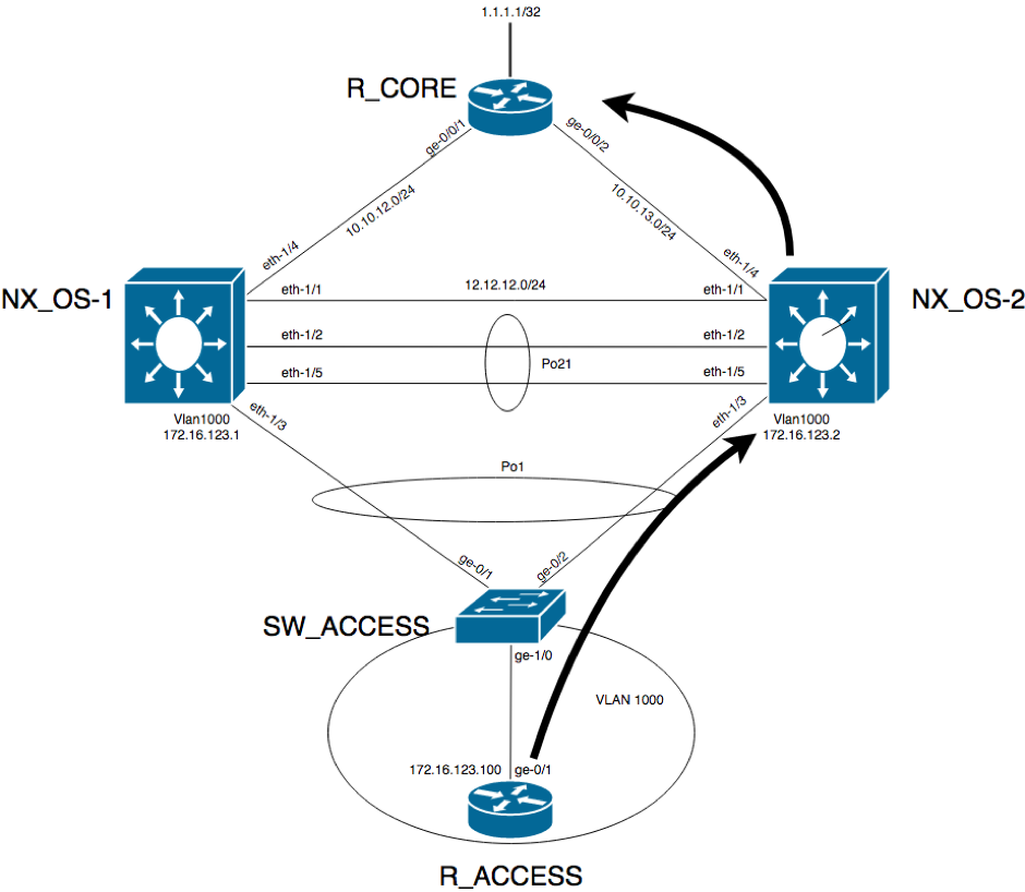
The diagram below shows when the traffic hits NX_OS-2:
When the traffic takes this path, the ACL matches the packet and logs it:
R_CORE#show ip access-lists
 Extended IP access list VIA_NX_OS-1
 10 permit icmp host 172.16.123.100 host 1.1.1.1 log-input (5 matches)
 20 permit ip any any (25 matches)
 Extended IP access list VIA_NX_OS-2
 10 permit icmp host 172.16.123.100 host 1.1.1.1 log-input (5 matches)
 20 permit ip any any (8 matches)
 R_CORE#
As you can, see whenever the traffic goes to NX_OS-2, the traffic is routed directly to the destination according to the routing table.
This is how the ARP/MAC table looks on NX_OS-1, the master VRRP:
NX_OS-1# show ip arp

Flags: * - Adjacencies learnt on non-active FHRP router
 + - Adjacencies synced via CFSoE
 # - Adjacencies Throttled for Glean
 CP - Added via L2RIB, Control plane Adjacencies
 PS - Added via L2RIB, Peer Sync
 RO - Dervied from L2RIB Peer Sync Entry
 D - Static Adjacencies attached to down interface

IP ARP Table for context default
 Total number of entries: 3
 Address Age MAC Address Interface Flags
 10.10.12.1 00:01:22 fa16.3ecd.b31a Ethernet1/4
 172.16.123.2 00:00:09 5e00.0001.0007 Vlan1000
 172.16.123.254 - 0000.5e00.0101 Vlan1000
 NX_OS-1# show mac address-table
 Legend:
 * - primary entry, G - Gateway MAC, (R) - Routed MAC, O - Overlay MAC
 age - seconds since last seen,+ - primary entry using vPC Peer-Link,
 (T) - True, (F) - False, C - ControlPlane MAC
 VLAN MAC Address Type age Secure NTFY Ports
 ---------+-----------------+--------+---------+------+----+------------------
 G 1000 0000.5e00.0101 static - F F sup-eth1(R)
 G - 5e00.0000.0007 static - F F sup-eth1(R)
 G 1000 5e00.0000.0007 static - F F sup-eth1(R)
 * 1000 5e00.0001.0007 static - F F vPC Peer-Link(R)
 NX_OS-1#
And on NX_OS-2:
NX_OS-2# show ip arp

Flags: * - Adjacencies learnt on non-active FHRP router
 + - Adjacencies synced via CFSoE
 # - Adjacencies Throttled for Glean
 CP - Added via L2RIB, Control plane Adjacencies
 PS - Added via L2RIB, Peer Sync
 RO - Dervied from L2RIB Peer Sync Entry
 D - Static Adjacencies attached to down interface

IP ARP Table for context default
 Total number of entries: 3
 Address Age MAC Address Interface Flags
 10.10.13.1 00:15:50 fa16.3ee0.57bf Ethernet1/4
 172.16.123.1 00:01:18 5e00.0000.0007 Vlan1000
 172.16.123.254 00:00:05 0000.5e00.0101 Vlan1000
 NX_OS-2# show mac address-table
 Legend:
 * - primary entry, G - Gateway MAC, (R) - Routed MAC, O - Overlay MAC
 age - seconds since last seen,+ - primary entry using vPC Peer-Link,
 (T) - True, (F) - False, C - ControlPlane MAC
 VLAN MAC Address Type age Secure NTFY Ports
 ---------+-----------------+--------+---------+------+----+------------------
 G 1000 0000.5e00.0101 static - F F vPC Peer-Link(R)
 * 1000 5e00.0000.0007 static - F F vPC Peer-Link(R)
 G - 5e00.0001.0007 static - F F sup-eth1(R)
 G 1000 5e00.0001.0007 static - F F sup-eth1(R)
 NX_OS-2#
On the active router at control plane, the virtual MAC points to sup-eth1(R), while on the backup router at control plane, the virtual MAC points to the vPC peer-link and this is a good way to determine which router is the active and which is the backup on control plane level.
As mentioned at the beginning of the article, you do not need to do anything to benefit from this mode of operation of FHRP in combination with vPCs.
Thank you to Paris Arau for his contributions to this article.
Key takeawaysKey takeaways are generated with AI assistance. Because automated summaries can occasionally contain errors or miss important context, always refer to the full blog post for complete information.
This article explains how Virtual Port-Channel (vPC) enables First Hop Redundancy Protocols (FHRP) such as HSRP and VRRP to operate active-active in the data plane while maintaining active-backup behavior in the control plane, solving inefficiencies in traffic distribution across redundant uplinks. In a Nexus vPC deployment the vPC peer devices use a Gateway (G) bit on the FHRP virtual MAC so both peers can forward traffic (data plane active-active) while only the control-plane master replies to ARP/VRRP control traffic, preserving ARP reply consistency and interoperability. The write-up shows a VRRP example across two Nexus devices with port-channels and OSPF, demonstrates traffic hitting either peer and being forwarded correctly, and highlights that no extra configuration is required to enable this vPC built-in behavior.
How does vPC make FHRPs like VRRP or HSRP operate active-active at the data plane while keeping active-backup at the control plane?
vPC imposes the Gateway (G) bit for the FHRP virtual MAC in the MAC address table on both vPC peer devices so both peers can forward traffic for the virtual IP (data plane active-active). At the control plane, FHRP behavior remains active-backup: only the control-plane active/master router replies to ARP requests with the virtual MAC. If the backup receives an ARP request it forwards that request to the active router across the vPC peer-link, and the active router replies. This design requires no additional configuration — the vPC built-in mechanism enforces the G bit and MAC behavior.
In the VRRP example, how can you tell which Nexus is control-plane master versus backup using show commands?
You can inspect VRRP and vPC outputs: the VRRP detail on the Nexus that is control-plane master shows State is Master and indicates the Virtual IP and Virtual MAC (for example, NX_OS-1 showing Master for VLAN1000 and virtual IP 172.16.123.254). The vPC show output indicates the vPC role (primary/secondary). Additionally, the MAC address-table differs: on the control-plane active router the virtual MAC is associated with the supervisor uplink (sup-eth1(R)), while on the backup router the virtual MAC points to the vPC peer-link. Those differences let you determine which device is active at control plane and which is backup.
Does enabling active-active forwarding for FHRP over vPC require extra configuration on Nexus devices?
No additional configuration is required to gain the active-active data plane behavior for FHRPs when using vPC. The article states this feature is built-in to vPC: vPC automatically imposes the Gateway (G) bit on the FHRP virtual MAC in the MAC address tables of both vPC peers, enabling both devices to forward traffic for the virtual IP while preserving active-backup control-plane behavior. The write-up emphasizes that the vPC peer-link handles ARP forwarding from the backup to the active router without special configuration.
Map your network with user-defined links in Integrity X to define and manage custom relationships, such as dual-stack and NAT environments.
Read more
We’re using cookies on this website to improve your experience. Cookies help us learn how you interact with our website and remember you when you come back so we can tailor it to your interests.
To learn more about cookies and how we use them, read our cookie notice.
Some cookies are essential, while others help us to improve your experience by giving us insight into how you are using our website. You may adjust your preferences for non-essential cookies below.
To learn more about cookies and how we use them, read our cookie notice. You can also review our privacy policy for more details on the personal data we collect, use, hold, and disclose when you visit our website or use our products and services.
Functional cookies
Functional cookies are essential cookies that allow us to remember choices or changes you have made (such as to language settings or your choices regarding the use of cookies). These cookies cannot be turned off since they are essential for the operation of our Websites.
Analytics cookies
Analytics cookies are non-essential cookies that collect information on how visitors use our Websites. We use this information with your consent to measure the number of visitors to our Websites, determine whether specific content or communication has been viewed, and to help us improve our Websites and communication. These cookies can be turned off.
Personalisation Storage
Personalisation cookies are non-essential cookies that collect information when you fill out a form on this website. We only use this information with your consent to pre-fill other forms on the site. These cookies can be turned off.
Marketing cookies
Marketing cookies are cookies that are placed by third parties to collect information about your visits and actions on our Websites so that they or we can deliver ads to you later, such as when you are on certain third-party sites or platforms. These cookies may be used by those third parties to build a profile of your interests and show you relevant ads on other websites. These cookies also enable visitors to our Websites to share content on social networks and to enable and evaluate interactions with our communication and social media tools. These cookies can be turned off.