
Palo Alto Networks Advanced Administration Tips


Notice: This blog post was originally published on Indeni before its acquisition by BlueCat.
The content reflects the expertise and perspectives of the Indeni team at the time of writing. While some references may be outdated, the insights remain valuable. For the latest updates and solutions, explore the rest of our blog
Introduction
The Palo Alto Networks next-generation firewalls are a part of a security platform that provides a plethora of configuration options within its devices. The results from adequately utilizing the available configuration options provide a strengthened security posture in respect to existing and future information security challenges or organization mandates.
Thus, the installation of the Palo Alto Networks next-generation firewalls in your information technology infrastructure is likely imminent or already underway. Accordingly, increasing your familiarity with the Palo Alto Networks firewalls is wise, so you can ensure you have the capabilities to support daily operations.
Scenario Set-Up
To help with your understanding for this blog, a sample environment has been created utilizing a Layer 3 configuration. Unlike the VWire Interface configuration, the firewall utilizes a Layer 3 configuration. Therefore, the firewall plays the role of the gateway for the connected networks.
In this scenario, the firewall is a VM-100 virtual next-generation firewall within a virtualized environment and connects to the two internal networks that have one virtual desktop computer each and the Internet.
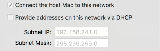
Note: The instance of VMware environment is configured with the two private networks/vmnets that each has the host physical computer as the gateway for the virtual desktops computers on the respective subnet and a connection to the Internet via a dedicated vmnet.
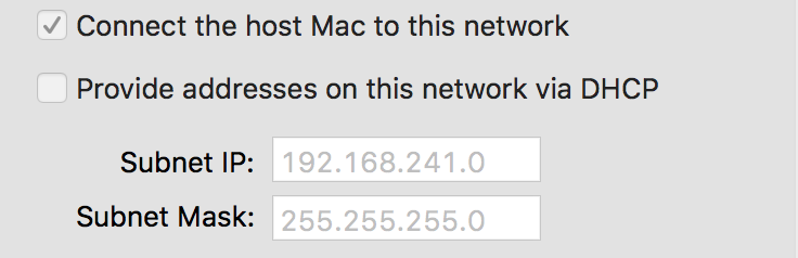
Additionally, the internet facing interface is configured with a static IP address on the same range as the example internet router to provide external connectivity to the firewall and the virtual desktops computers. Lastly, the firewall has already been registered via Palo Alto Networks Support Portal.
Note: You can complete this configuration with any physical Palo Alto Networks next-generation firewalls and host computers or via the Palo Alto Networks FUEL User Group Virtual Test Lab.
Network Architecture:
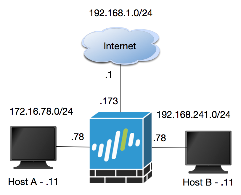
Internet Interface (Eth 1/1): 192.168.1.173/24
Internet Router: 192.168.1.1
Subnet: 192.168.1.0/24
Zone: Internet
Host A: 172.16.78.11
Gateway (Eth 1/2): 172.16.78.78/24
Subnet: 172.16.78.0/24
Zone: 78-Zone
Host B: 192.168.241.11
Gateway (Eth 1/3): 192.168.241.78/24
Subnet: 192.168.241.0/24
Zone: 241-Zone
General Settings
During the configuring your firewall, you can update many General Settings including your hostname (the default is model name for each firewall, ex. VM-100 or PA-3020), the login banner, timezone, locale, and time.
- Go to Device>Setup>Management and click on the gear symbol on the General Settings ribbon
- Update with Hostname field (ex. Indeni-Palo-Ex)
- Update with Login Banner field
- Update with Time Zone field
- Update with Locale field
- Update with Date field
- Update with Time field
- Click the OK button

Interface Management
The interface type that we will use to support traffic for the network devices is a Layer 3 Interface:
- Layer 3 – Operates at Layer 3 and will have an IP address and be attached to the virtual router on the NGFW.
Furthermore, the interfaces can be configured via Interface Management Profiles to run specific services when being managed via IP address. A few of services that we will use are HTTPS, Ping, and SSH.
Now we’ll create one profile to support ping, which will be used for the ethernet1/1 (external connection) and the ethernet1/2 and another profile to support https, ping, and ssh for ethernet1/3.
- Go to Network>Network Profiles>Interface Mgmt and click Add
- Update the Name field with the designated name
Example (Access):
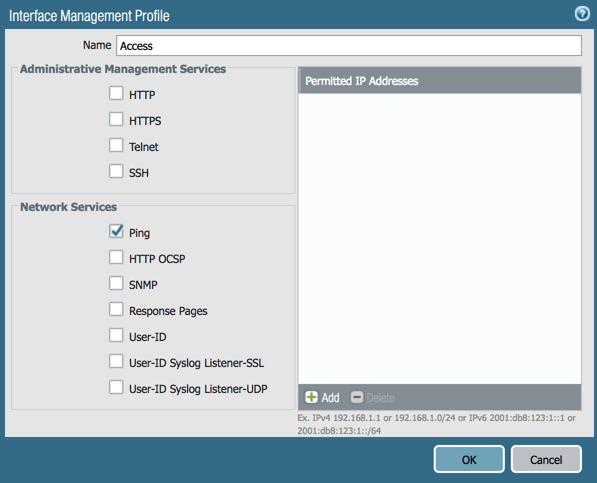
Example (Access-Admin):
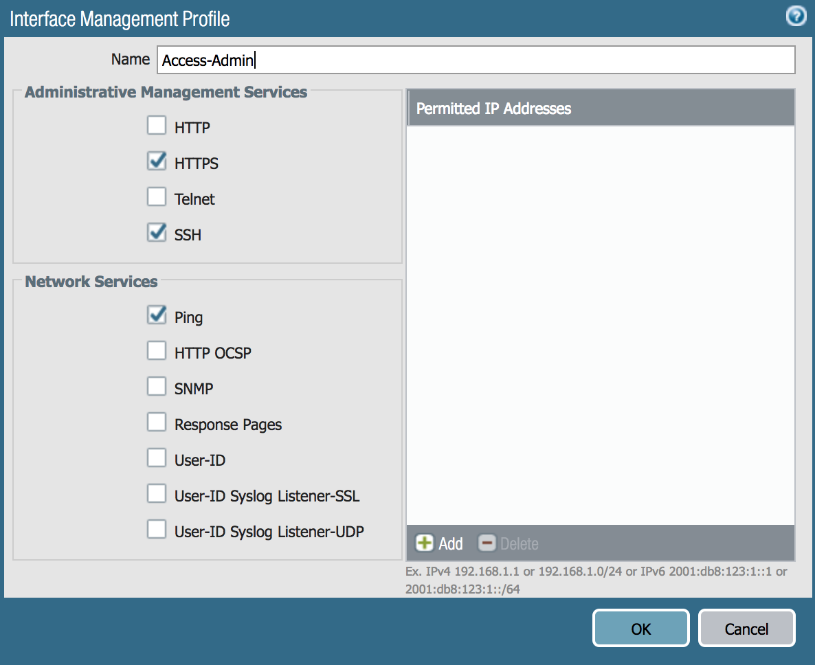
Note: The subnets accessing the services on these interfaces can be specified within the Permitted IP Addresses field.
Let’s utilize ethernet1/1 (external connection), ethernet1/2 and ethernet1/3 as a part of a Layer3.
- Go to Network>Interfaces and click on ethernet1/1, ethernet1/2 and ethernet1/3 and change the Interface Type dropdown to Layer3
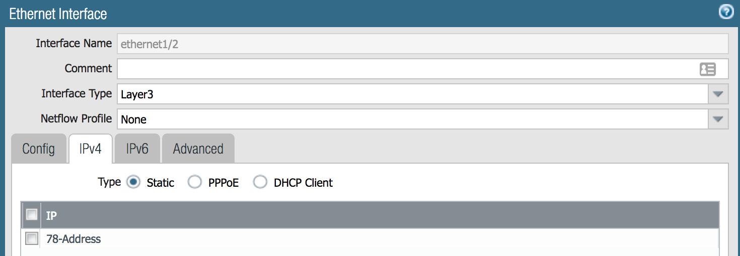
- Click the IPv4 tab, click the Add button, and add in the interface IP address (the IP type is Static by default and the address object has already been created with the IP
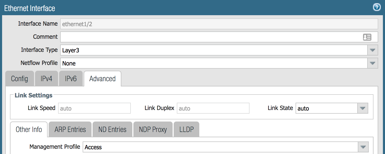
- Click the Advanced tab and update the Management Profile field with the designated Interface Management Profile
Zone Referencing
Zones reference certain traffic and is comprised of one or more interfaces on the NGFW. We will utilize Layer 3 Zones for the interfaces that were previously configured types.
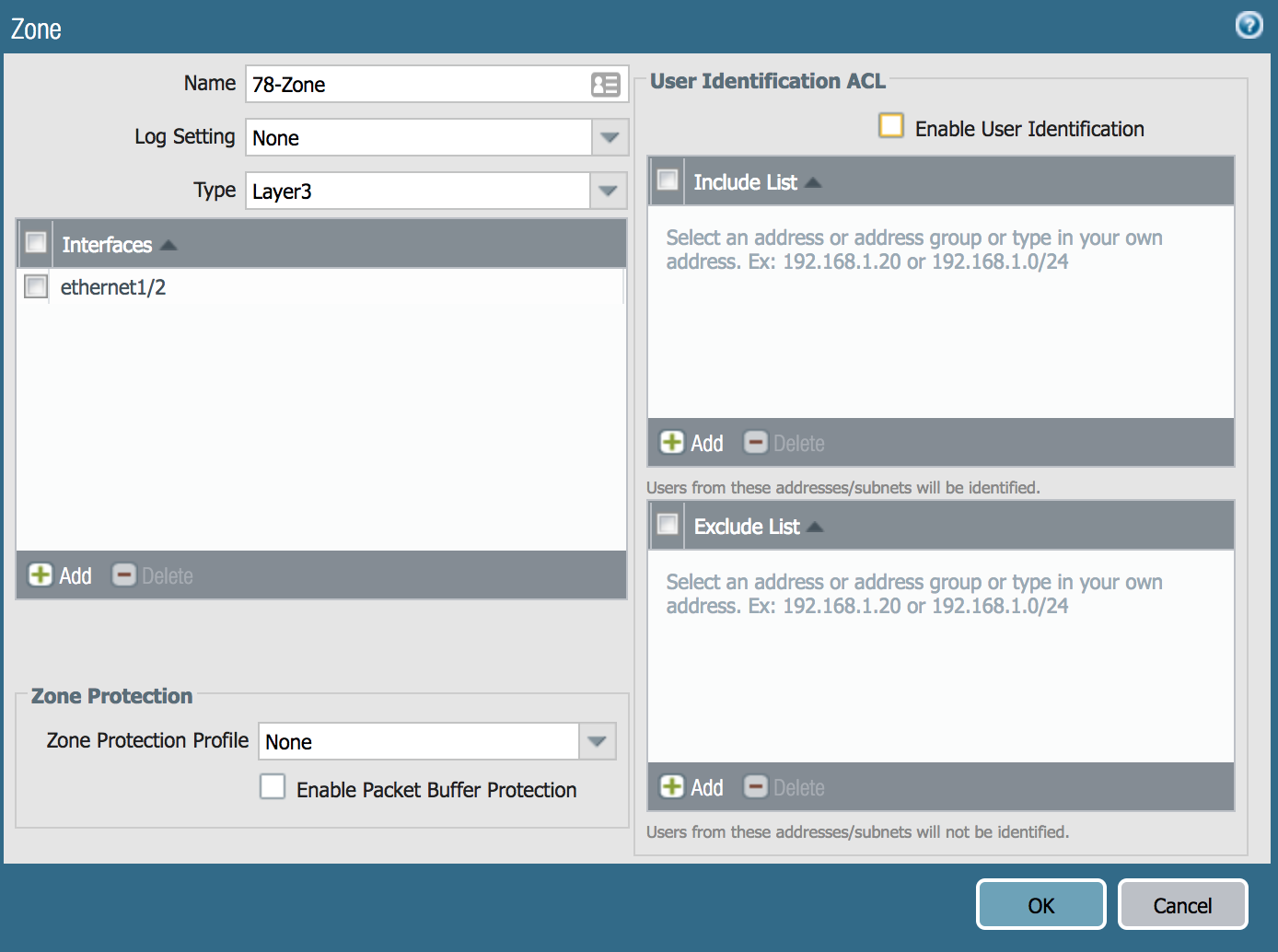
Now, we still change ethernet1/1 to a Zone named Internet, ethernet1/2 to a Zone named 78-Zone, and ethernet1/3 to a Zone named 241-Zone.
- Go to Network>Zones and click Add
- Update the Name field
- Change the Type dropdown to Layer 3, click Add in the Interfaces section and click the OK button
How To Create A Virtual Router
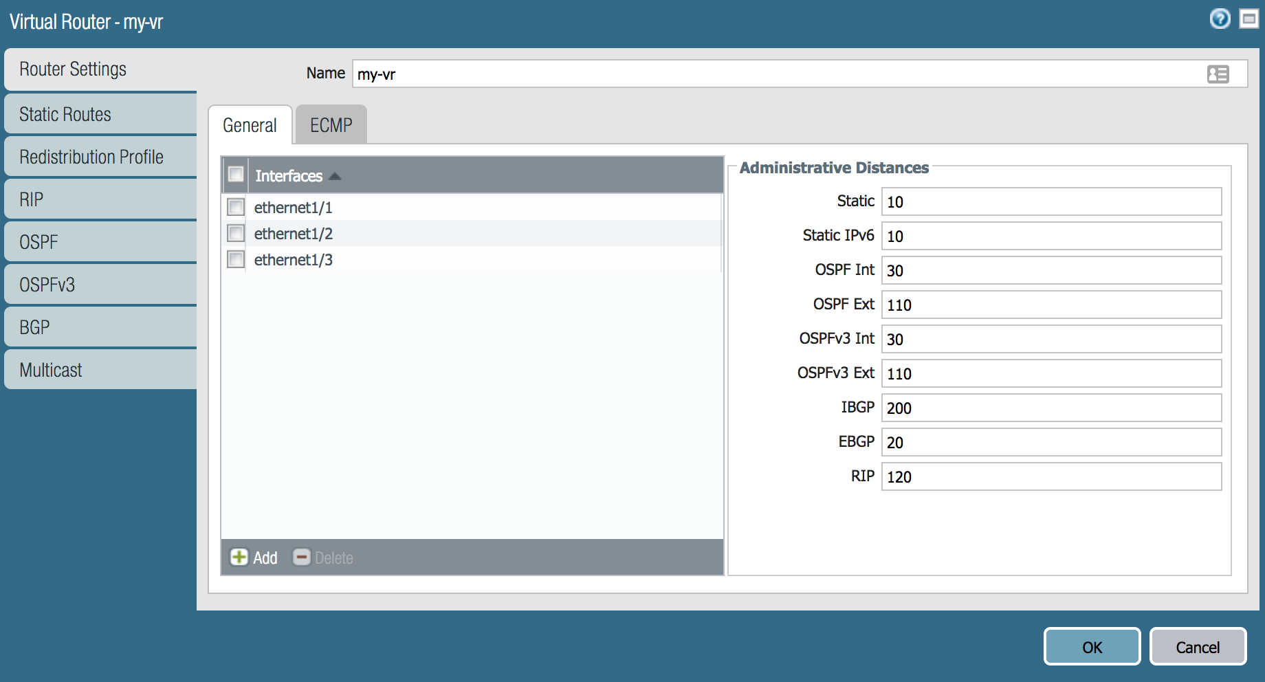
- Go to Network>Virtual Routers and click Add
- Under the Router Settings, update the Name field
- Under the General tab, click Add and select ethernet1/1 (and repeat the process for ethernet1/2 and ethernet1/3)
- Under the Static Routes tab, click Add under the IPv4 tab
- Update the Name field (ex. Default Internet)
- Update the Destination field (0.0.0.0/0)
- Update the Interface field (ethernet1/1)
- Update the Next Hop field with type (for this instance, it is IP Address)
- Enter IP Address of the Next Hop (192.168.1.1)
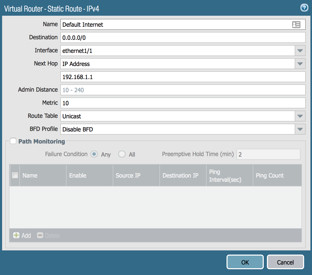
- Click the Add button for the Static Route window
- Click the Add button for the Virtual Router window
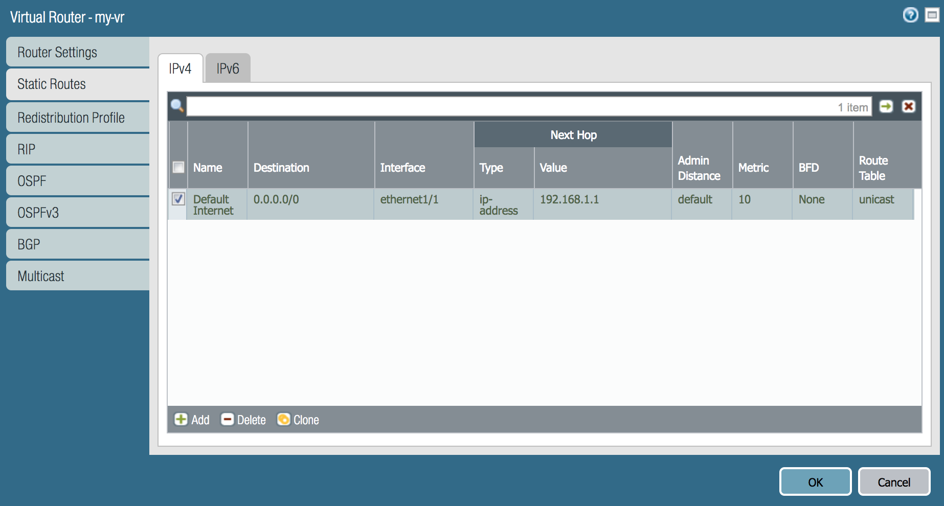


Note: By adding the interfaces, the subnets for the interfaces will be added as connected routes in the virtual router instance under More Runtime Stats.
Network Address Translation (NAT)
NAT allows you to conceal one or more IP addresses and display designated IP addresses.
Let’s create a policy to the NAT the LAN traffic (78-Zone & 241-Zone) to the ethernet1/1 when the destination is the Internet zone
- Go to Policies>NAT and click Add
- Under the General tab, update the Name field
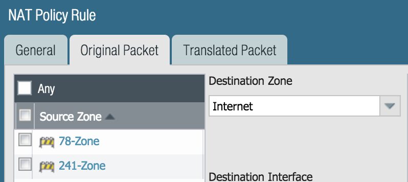
- Under the Original Packet tab:
- Add 78-Zone and 241-Zone in the Source Zone box by clicking Add for each zone
- Change the Destination Zone drop-down to Internet
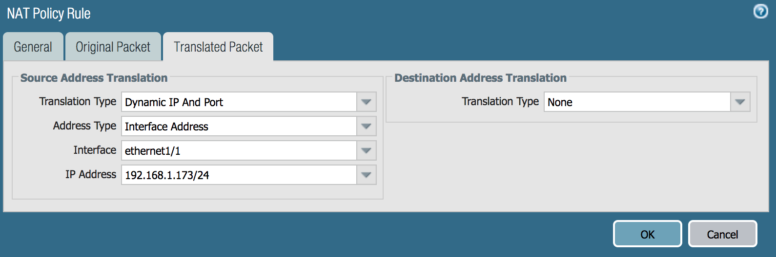
- Under the Translated Packet tab
- Change the Translation Type drop-down to Dynamic IP and Port
- Change the Address Type drop-down to Interface Address
- Change the Interface drop-down to ethernet1/1
- Change the IP Address drop-down to the interface IP (ex. 192.168.1.173/24)
- Click the Ok button
How To Create Security Policies
Security policies allow or deny traffic. They also allow the traffic that will correspond to the NAT policy the previous section
Let’s create a two security policies. One security policy will allow traffic between the LAN zones (78-Zone & 241-Zone) and another security policy that will allow the LAN traffic to the Internet Zone.
- Go to Policies>Security, click Add, and update the two security policies:
- General>Name field (Routing-LAN/LAN-to-Internet)
- Source>Source Zone, click Add (select 78-Zone & 241-Zone for both security policies)
- Destination>Destination Zone, click Add (select 78-Zone & 241-Zone/Internet)
- Click the OK button for the Security Policy

How To Commit Configuration Changes
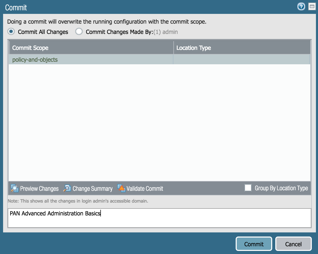
The changes made to the firewall have been added to the candidate config, but need to be committed to add them to the running config. To add changes to the running config:
- Click Commit
- Click the Commit button on the bottom right of the window
Advanced Administration Results
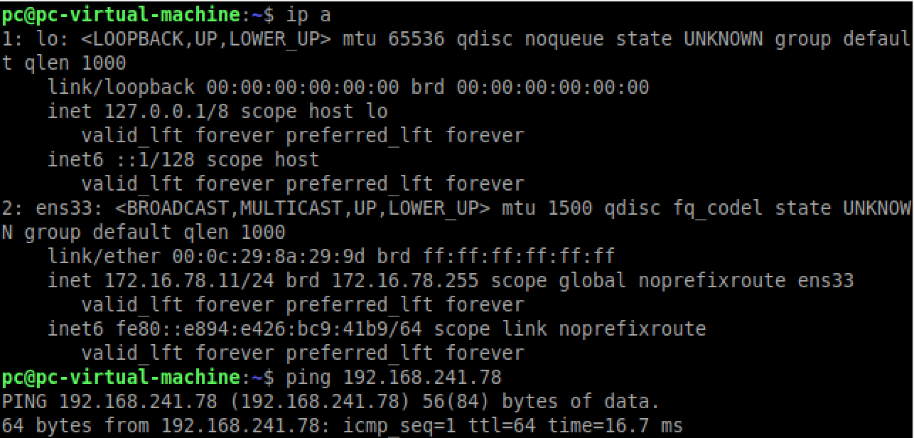
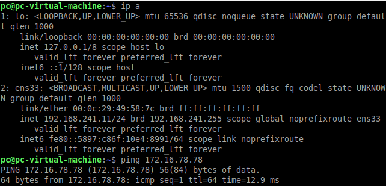
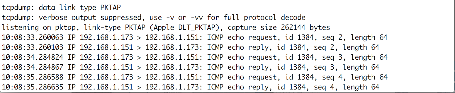
Here are the results of your advanced administration:

What We Learned
You just learned about Interface Management Profiles, Layer 3 Interfaces and Zones, Virtual Routers, NAT policies, and creating the Security policies that allows the traffic matching the NAT policy. For more guides, tips, and how-to guides, join Indeni Crowd. Indeni Crowd includes learning paths and challenges which grant points that you can redeem for epic rewards!
 Key takeawaysKey takeaways are generated with AI assistance. Because automated summaries can occasionally contain errors or miss important context, always refer to the full blog post for complete information.
This article walks through configuring a Palo Alto Networks VM-100 next-generation firewall in a Layer 3 topology to act as the gateway between two internal subnets and the Internet. It addresses the real-world problem of securely connecting internal networks to the Internet by covering device general settings, interface management profiles, Layer 3 interfaces and zones, virtual router and static route setup, NAT for outbound traffic, and security policies to permit LAN-to-LAN and LAN-to-Internet communication. The outcome is a committed running configuration where interfaces, zones, routes, NAT, and security rules are in place so internal hosts can reach each other and the Internet while allowing managed access to firewall management services.
What are the key interface and zone settings required to place the firewall into a Layer 3 gateway role in this lab environment?
To configure the firewall as a Layer 3 gateway you must change ethernet1/1, ethernet1/2, and ethernet1/3 to Interface Type = Layer3, assign each interface an IPv4 static address (via the IPv4 tab), and attach an Interface Management Profile on the Advanced tab to permit services such as HTTPS, Ping, or SSH. Then create Layer 3 Zones (Internet, 78-Zone, 241-Zone) under Network > Zones and add the corresponding interfaces to each zone. These steps ensure each interface has an IP, is part of the virtual router’s connected routes, and is associated with the appropriate security zone for policy enforcement.
How is outbound Internet access achieved for hosts on the 78-Zone and 241-Zone subnets?
Outbound Internet access is accomplished by creating a static default route in a Virtual Router and a NAT policy plus corresponding security policies. In the Virtual Router, add ethernet1/1, ethernet1/2, and ethernet1/3 as interfaces and create a static route for 0.0.0.0/0 using ethernet1/1 with the Internet router IP (192.168.1.1) as the next-hop. Then under Policies > NAT create a Dynamic IP and Port rule that translates traffic from source zones 78-Zone and 241-Zone to the interface address of ethernet1/1 (example 192.168.1.173). Finally create Security policies permitting traffic from the LAN zones to the Internet zone so translated packets are allowed.
Which management and general settings should be updated during initial firewall setup in this scenario?
During initial setup you should update General Settings under Device > Setup > Management: set a meaningful hostname (instead of the default model name), configure a login banner, select the correct time zone and locale, and set the date and time. Additionally, define Interface Management Profiles (Network > Network Profiles > Interface Mgmt) to control permitted management services and optionally restrict permitted IP addresses for those services. These changes improve administrative clarity, ensure correct timestamps for logs, and control which services and source IPs can manage the firewall interfaces.
Related content

Get answers from the LiveNX data you already have with LiveAssist
Learn how LiveAssist, the AI-powered add-on for LiveNX, turns your network data into fast, guided answers, with value you can see in days.

LiveWire GEN3 device offerings
BlueCat LiveWire is a packet capture and network forensics platform that provides deep packet-level visibility across hybrid enterprise environments to help…

Get total control of your DDI infrastructure with Micetro’s unified API
Stop juggling between network tools and use Micetro’s RESTful API for complete control over your DDI infrastructure and cloud environment.

BlueCat MCP servers bring network intelligence to your AI assistant
Our MCP servers provide a standard integration layer that makes it easy to connect the AI tools you already use to BlueCat products.