- Glossary
- What is the OSI model? It standardizes how computer networks communicate
What is the OSI model? It standardizes how computer networks communicate
The OSI model is a conceptual model that provides a universal standard for how computing devices communicate across networks, with seven abstract layers.
Last updated: January 6, 2026
The Open Systems Interconnection (OSI) model is a conceptual model that provides a universal standard for how computing devices communicate across networks.
What is the OSI model? Created by the ISO, or the International Organization for Standardization, it divides communication across computer networks into seven abstract layers that are stacked upon each other. Each layer performs a distinct function in network communication and communicates with the layers above and below it.
The model applies regardless of any system’s particular underlying technology or the protocol suites that it uses. It’s intended to be interoperable for all systems that use standard communication protocols.
This glossary entry will explore each of the seven layers of the OSI model in depth. It will also touch on the value of the OSI model and how it differs from other network communication models, such as TCP/IP. Finally, it will highlight the role of DNS in it.
The OSI model layers
There are seven abstract layers of the OSI model. Need an easy way to remember them? Try this mnemonic device: All People Seem To Need Data Processing. (And check out some other great OSI mnemonic devices.)
| All | Application (Layer 7) |
|---|---|
| People | Presentation (Layer 6) |
| Seem | Session (Layer 5) |
| To | Transport (Layer 4) |
| Need | Network (Layer 3) |
| Data | Data Link (Layer 2) |
| Processing | Physical (Layer 1) |
To best understand the model, it’s often easier to start at the top, with Layer 7, the application layer, and work your way down.
Layer 7: The application layer
This layer is closest to the end user. However, it’s important to note that software applications themselves (like, say, Microsoft Word) aren’t part of this layer. Rather, the application layer encompasses the protocols that applications rely on to perform their job and communicate data to end users.
Protocols that are part of the application layer would include Hypertext Transfer Protocol (HTTP) if you’re using web browsers, Simple Mail Transfer Protocol (SMTP) if you’re using an email client, File Transfer Protocol (FTP) if you’re transferring files, as well as a number of others.
DNS resides at Layer 7 as well. More on that in a moment.
Layer 6: The presentation layer
This layer configures data for the application layer into a format that it will accept. There are three ways in which it does this: translation, encryption (and decryption), and compression.
Translation converts all the binary 1’s and 0’s into machine-readable data. If devices are using different communication methods, the presentation layer translates the data into an understandable language for the receiving device at Layer 7.
Furthermore, if the connection is encrypted, Layer 6 adds encryption from the sender and decrypts for the receiver. As a result, the application layer receives unencrypted data. A prime example would be web browsers and servers using SSL, the encryption security protocol.
Finally, the presentation layer is responsible for compressing data that it gets from Layer 7 before it sends it down the stack to Layer 5. For example, it might compress a 30-megabyte file down to a 10-megabyte file before transferring it to the session layer. Compression bolsters efficiency and speed, which becomes especially important when involving large video and audio files.
Layer 5: The session layer
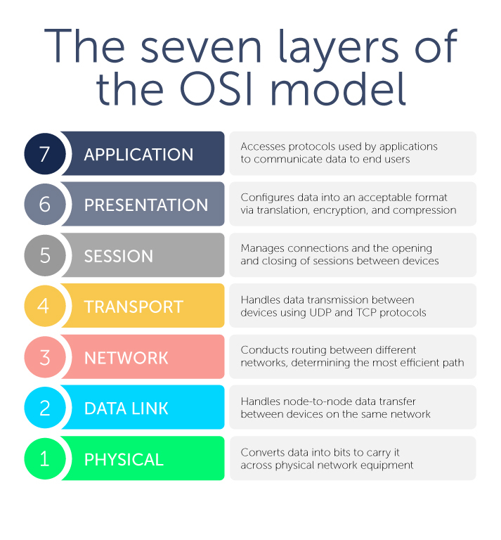
This layer is about managing connections—also known as sessions—between two or more devices. In particular, it controls when these communication sessions start and stop. Using ports defined in Layer 4, Layer 5 ensures that sessions stay open to transfer all the necessary data and then closes sessions when they’re done.
The session layer handles user authentication from usernames and passwords, as well as any other authentication protocols, and user logoff to terminate sessions.
Layer 4: The transport layer
Next, this layer handles data transmission between devices using User Datagram Protocol (UDP) or Transmission Control Protocol (TCP). If data units are big and exceed maximum packet sizes, they are split up into smaller pieces called segments before they are sent down the stack to Layer 3. Receiving devices also reassemble these segments at Layer 3.
Segments have a sequence number associated with them. As data packets are split into smaller chunks, they have to be put back in the right order for reassembly.
Layer 4 also conducts flow control and error control. Flow control ensures that data is moving between senders and receivers at an optimal rate to ensure that a fast connection doesn’t overwhelm a slow one. A receiving device with a slower connection will acknowledge that “Yes, I’ve received these segments, go ahead and send the next ones.”
Meanwhile, error control checks the sums that are part of the packet to make sure that the data received is complete and correct.
Layer 4 also identifies which ports Layer 5 will use for conducting sessions for various functions. For example, DNS uses Port 53 which is nearly always open on systems, firewalls, and clients to transmit DNS queries. Web servers, meanwhile, use port 80 for HTTP or 443 for HTTPS.
Layer 3: The network layer
This layer is where routing occurs between different networks. The network layer breaks up the segments from Layer 4 into packets on the sending device, addresses them using IP addresses, transfers them to the destination, and then reassembles them on the receiving device. This layer determines which path is the most efficient for sending data packets where they need to go.
The primary protocols used here are the Internet Protocol (IPv4 or IPv6, which is how most internet traffic is sent, and the Internet Control Message Protocol (ICMP).
If two devices are communicating on the same network, such as a Local Area Network (LAN) in an office, activity at Layer 3 is not necessary.
Layer 2: The data link layer
On that note, the data link layer handles data transfer between two or more devices that are on the same network. It’s sometimes referred to as node-to-node data transfer. Ethernet is the most commonly used protocol at Layer 2.
Layer 2 takes packets from Layer 3 and breaks them into even smaller pieces called frames. While the addressing in a packet is an IP address, in a frame, it’s typically a media access control (MAC) address.
The data link layer is divided into two sublayers: The logical link control (LLC) sublayer and the MAC sublayer. The LLC sublayer provides the brains for Layer 2 as it controls synchronization, flow control, and error control. It sits above the MAC sublayer and liaises between the upper layers in the OSI stack and the protocols like Ethernet that operate at the MAC sublayer.
Layer 1: The physical layer
Finally, this layer encompasses equipment that carries data across networks, such as fibers and network switches. The physical layer is also where data is converted into bits, which are the binary computer strings of 1’s and 0’s. It converts the digital bits into electrical, radio, or optical signals.
It’s important to note that not all network communication has to use all seven OSI layers. Only Layers 1, 2, and 3 are mandatory.
The value of the OSI model
This isn’t the only model for a networking system; there is also the Internet protocol suite, or the TCP/IP model. But there are key differences. Created by the Department of Defense, TCP/IP is a simpler model of just four layers that collapses several layers of the OSI model.
TCP/IP is also specific to communication protocols used for the internet. TCP/IP specifies how data is transmitted over the internet, including how it is broken into packets, addressed, transmitted, routed, and received at its destination.
Meanwhile, the OSI reference model is more generic, independent of specific protocols, and useful for describing all forms of network communication.
Importantly, the OSI model provides a common language for troubleshooting in networked environments. Narrowing issues to a specific and commonly understood layer can often result in faster resolution.
It should also be noted that the OSI model is not infallible. Distributed denial-of-service (DDoS) attacks usually target specific layers of the OSI model.
How does DNS fit into the OSI model?
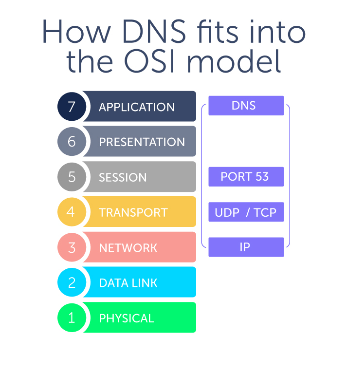
Is there a DNS OSI layer? In a word, no. DNS is an application layer protocol and sits with other protocols at Layer 7.
The Domain Name System (DNS) is a hierarchical naming system that allows communication across devices on a network. Most commonly, it translates human-readable domain names (like bluecatnetworks.com) to computer-friendly Internet Protocol (IP) addresses (like 104.239.197.100).
You direct your computer or smartphone, called a client device, to visit a website. To do so, your device sends out a DNS query or request to DNS servers. A stub resolver is the part of a client device that facilitates these requests, and stub resolvers reside at Layer 7.
However, DNS also makes use of UDP (and sometimes TCP) at Layer 4, both of which use IP at Layer 3. As a result, where DNS resides in the OSI model can sometimes cause confusion. Just because DNS traverses layers in the OSI model doesn’t mean it actually lives at those other layers.
Want to learn more about how to manage your DNS? BlueCat’s solution is the place to start.
Related content

MAC address vs IP address: What’s the difference?
MAC address vs IP address: One is a unique hardware identifier, while the other identifies a device’s network connection. Learn more with BlueCat.

Four major DNS attack types and how to mitigate them
In a DNS attack, DNS is compromised or used as a vector. Learn about the different attack types and how to prevent, detect, and mitigate them with BlueCat.

eBook: Network Rising
The gap between what the network team can deliver and what end-users need continues to widen. You need back-end DNS that supports all of your initiatives.